Club member Adrian Finch was our demonstrator this evening, and chose to make a motorbike engine – although he did warn that us that the project would not be completed until his next demonstration later in the year. There are a number of different components and Adrian explained how they would go together with reference to a simple drawing of the engine.

Set up on a table to one side was a selection of wood available to purchase from Bill Blyth of Bill’s Mill, based near Hanslope.
The Gearbox
As the gearbox ends are made of half cylinders, Adrian chose to do this with a split turning – two pieces of wood glued together to make a square blank about 125mm long, with some card between the two pieces to allow splitting once the shaping is done.
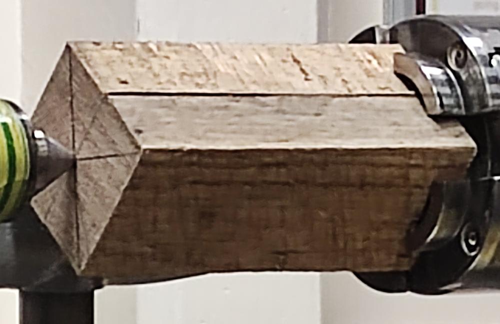
Held in the chuck, and with a live centre to steady it, the blank was turned round , with the diameter matching the height of the gearbox and then the live centre removed.This allowed Adrian to face off the end and put a groove in it.
He used a parting tool to make the cylinder length match the width of the gearbox and removed enough waste to make enough room to allow a matching groove to be put on the end. After this the assembly was parted off and carefully split to make two half-cylinders which will be mounted on the end of the gearbox casing.
The gearbox casing comprises a rectangular block of wood, drilled with a forstner bit to suit the tenon on the bottom of the cylinder.
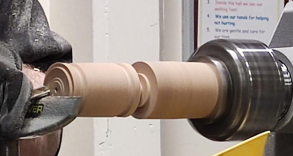
The Cylinder
For the cylinder, Adrian had glued a number of blocks of wood to make the blank (economical use of wood – it doesn’t grow on trees you know!) which he proceeded to mount between centres and turn to round.
The diameter was reduced to be no more than the width of the gearbox and a tenon put on the (bottom) end.
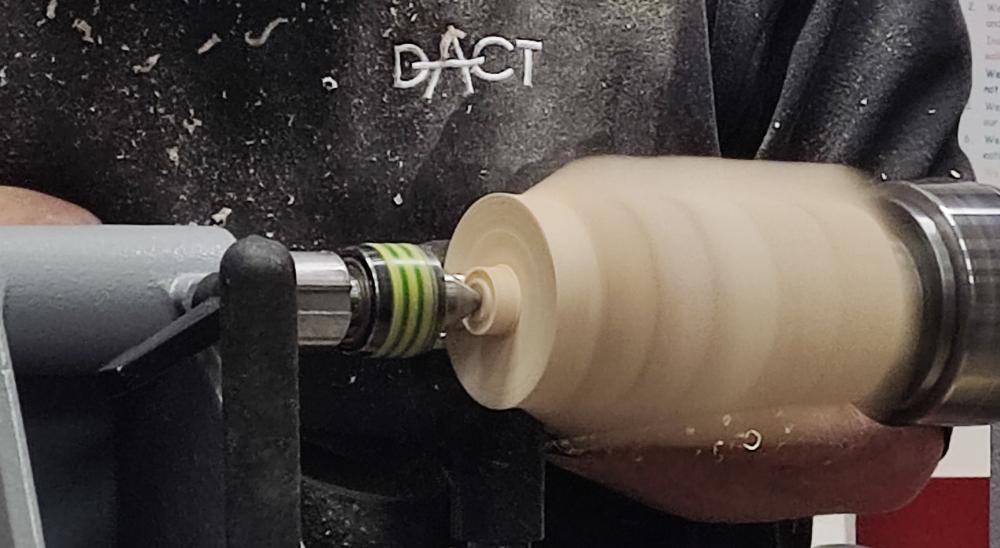
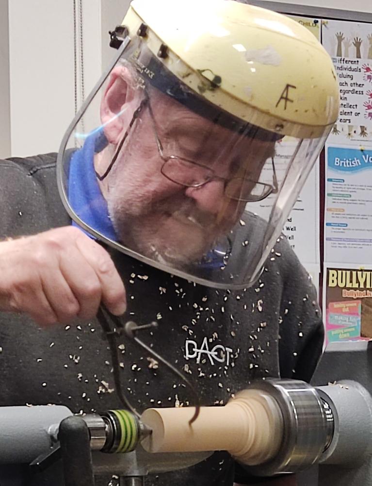
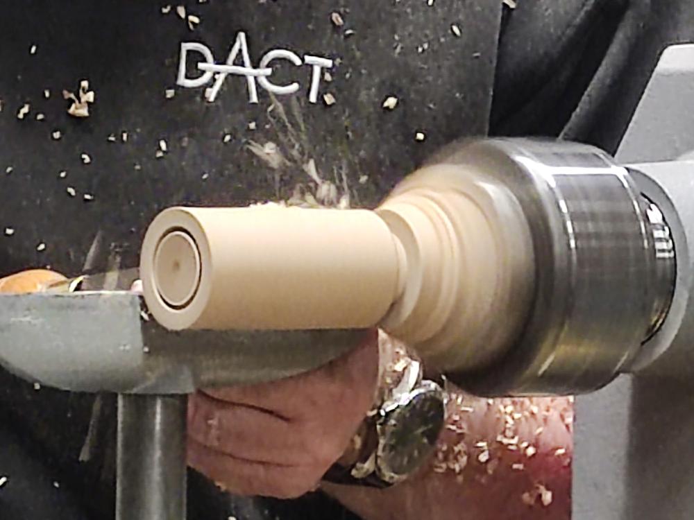
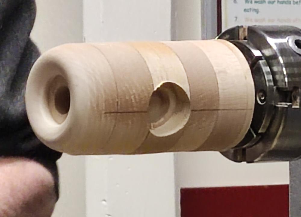
It was then reversed onto the chuck and the top of the cylinder drilled and shaped to form a spark plug recess and “threaded” hole.
With the lathe spindle locked off and brow furrowed in concentration, Adrian used a forstner bit to drill two holes on opposite sides of the cylinder – one for the exhaust, and one for the carburettor. Fortunately, he has a steadier hand than me and they came out neat and tidy!
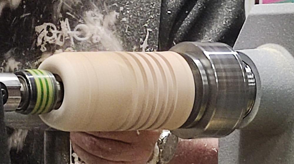
A quick overall sanding was followed by a parting tool to cut the first of the cylinder cooling fins centred on the two aforementioned inlet/outlet holes. From here, Adrian worked outwards until the cylinder was complete and sanding of the fins carried out.
The Spark Plug
Starting with a small rectangular blank held in the chuck, Adrian brought it to round and turned a tenon (the “thread” of the spark plug) to suit the hole drilled in the top of the cylinder, and formed a flange to emulate the gas seal of the plug.
It just remained, then, to shape the insulator and the terminal and to part off the spark plug.
The Magneto
With a few minutes left, Adrian quickly made a magneto for mounting behind the cylinder, basically a cylindrical affair with some detailing on the end, but which may need refining in Phase 2 later in the year.
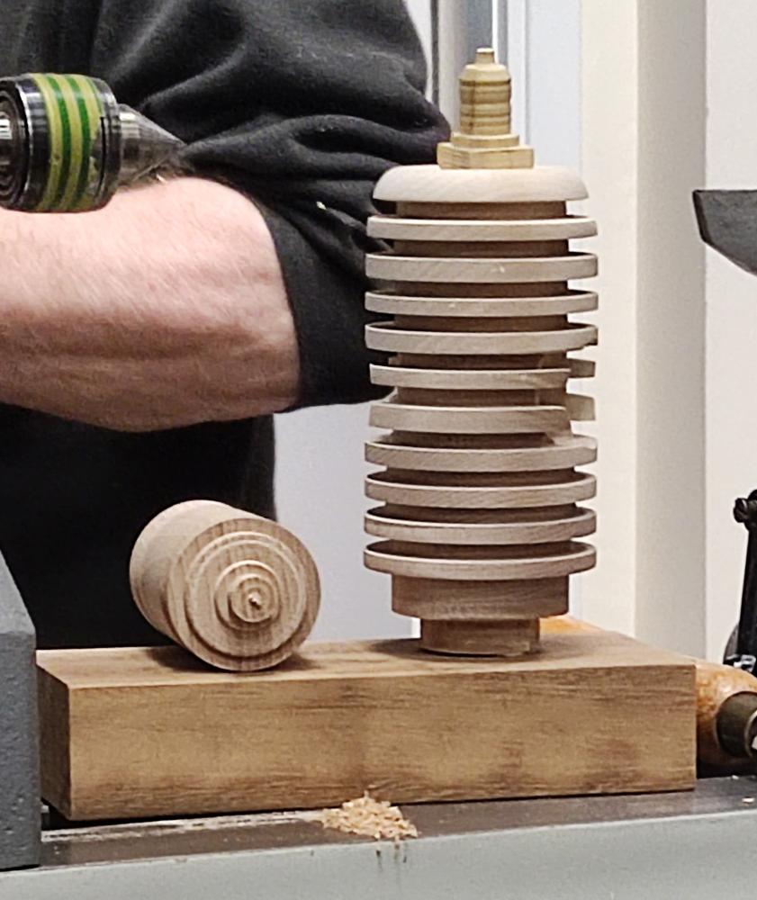
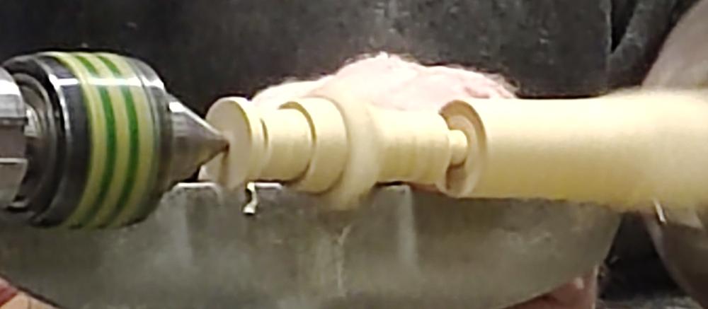
The completed Phase 1 is shown below, loosely assembled to show how it will all go together, although the rounded gearbox ends are missing for some reason – sorry about that!